Field of expertise:
Methods:
Application area:
Industry:
Introduction to the Problem
Bicycle helmets are an important part of safety of cyclists, especially at high speeds. It should be ensured that the buckle, as well as every other part of the helmet, does not suddenly fail, thus endangering the person wearing it. Using Ansys Mechanical software, the snap fit of a bicylce helmet buckle was simulated. Also, the behaviour of the buckle during this process was predicted.
Geometry
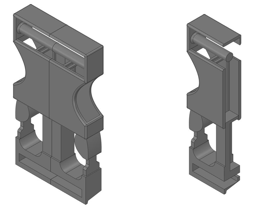
Original geometry of the buckle was adjusted in SpaceClaim software in order to create an appropriate geometry which could be used for simulation. For this purpose, small rounds and small surfaces were removed. Since the buckle has a symmetry plane, only one half of the geometry was used. As a result, computation time was significantly reduced. Complete geometry of the buckle can be seen in Figure 1a. The analysed half of the geometry is shown in Figure 1b. The buckle consists of two separate parts assembled by a snap fit method, where the parts are interlocked together.
Material
Material of the buckle was defined using Ansys GRANTA Selector software. Materials used for snap fit applications were searched through. The most appropriate material was chosen based on the specified requirements.
Semi Implicit Analysis
The two components of the buckle are assembled by snapping and speed is not affecting the forces. Thus a simple static analysis would be able to handle this calculation. However, observing the moment when the two parts are buckling on each other including time would be beneficial. For that reason, a semi-implicit analysis was conducted in Ansys Mechanical software to analyse the behaviour of the buckle.
A semi-implicit method is a hybrid method. It uses some features from both implicit and explicit finite element method [1]. This type of analysis was conducted simply by inserting a command in a static structural analysis, which transitions the analysis to a semi-implicit solution method at the moment when the convergence of the implicit solution fails. A semi-implicit analysis was in this case appropriate because snap-fit problems such as this one experience a brief period of large nonlinearities, which disable convergence in the implicit solution [1].
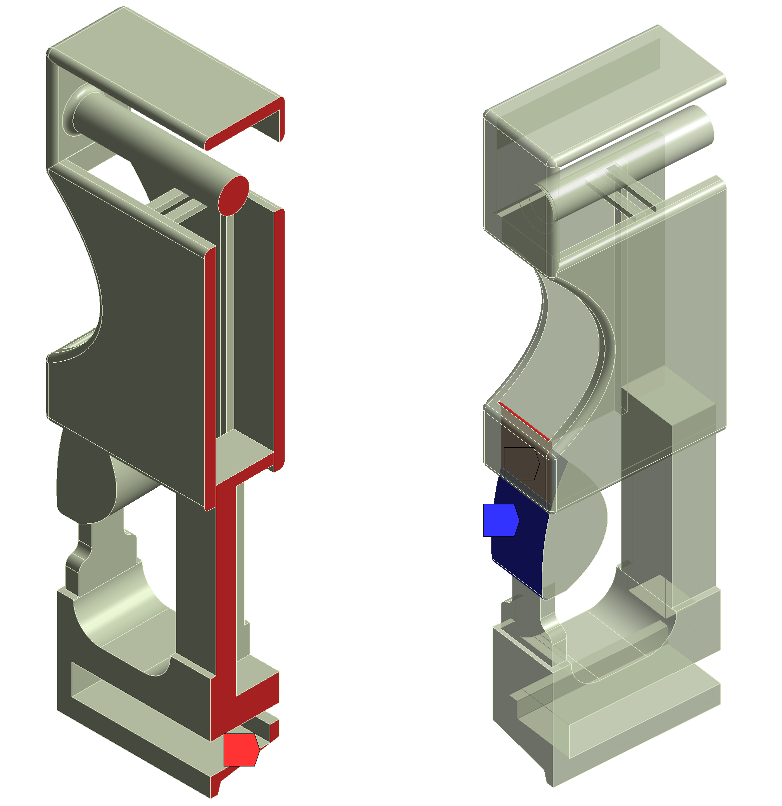
Taking into consideration that the geometry has a symmetry plane, only one half of the geometry was considered for the simulation. In order to properly conduct such kind of analysis, a symmetry region had to be defined. Faces defining the symmetry plane can be seen in Figure 2a, where they are marked red. As a next step, a frictional contact was defined between the two components of the assembly. This is shown in Figure 2b, where the faces of the contact are marked blue and red.
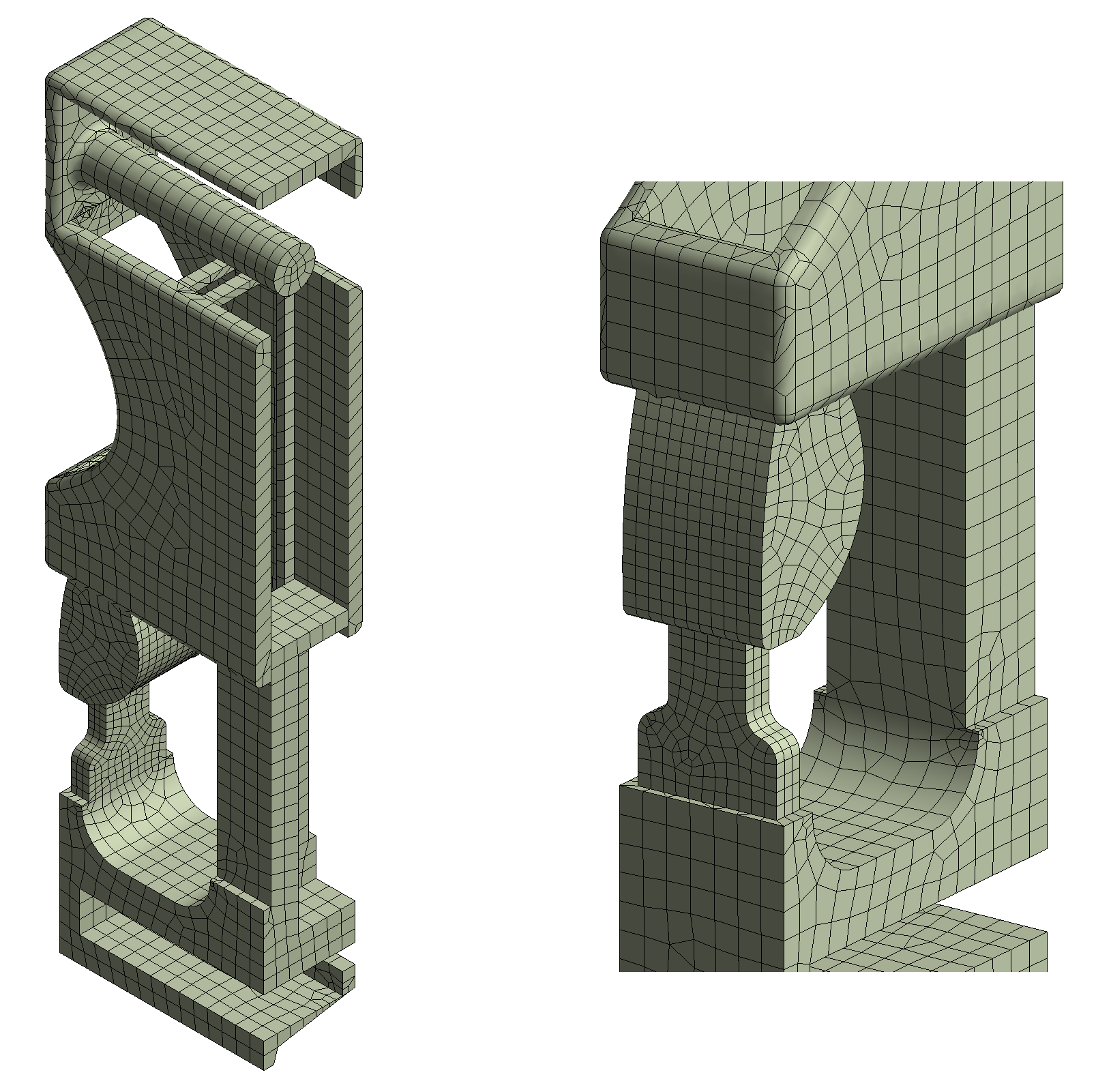
As a further step, mesh was generated on the model. Also, elements were refined on the contact faces of the components. The generated mesh can be seen in Figure 3a, while a detail of the refined mesh can be seen in Figure 3b.
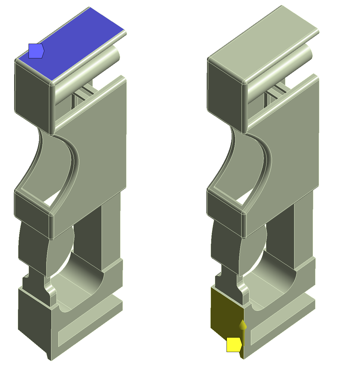
Top surface of the upper component was fixed, as can be seen marked blue in Figure 4a. A displacement was defined on a surface of the lower component, marked yellow in Figure 4b. Value of the applied displacement was 2.72 mm. This is just enough for the lower component to interlock with the upper component of the buckle.
Results of the Semi Implicit Analysis and Discussion
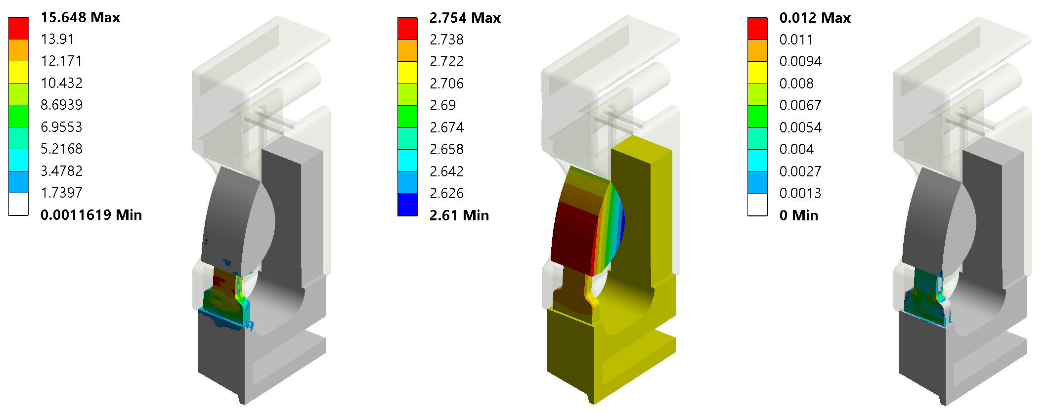
Equivalent stress, total deformation and equivalent plastic strain results were obtained for the buckle assembly model. Results on the lower component of the assembly can be seen in Figure 5. Equivalent stress distribution is shown in Figure 5a, total deformation distribution in Figure 5b and plastic strain distribution in Figure 5c.
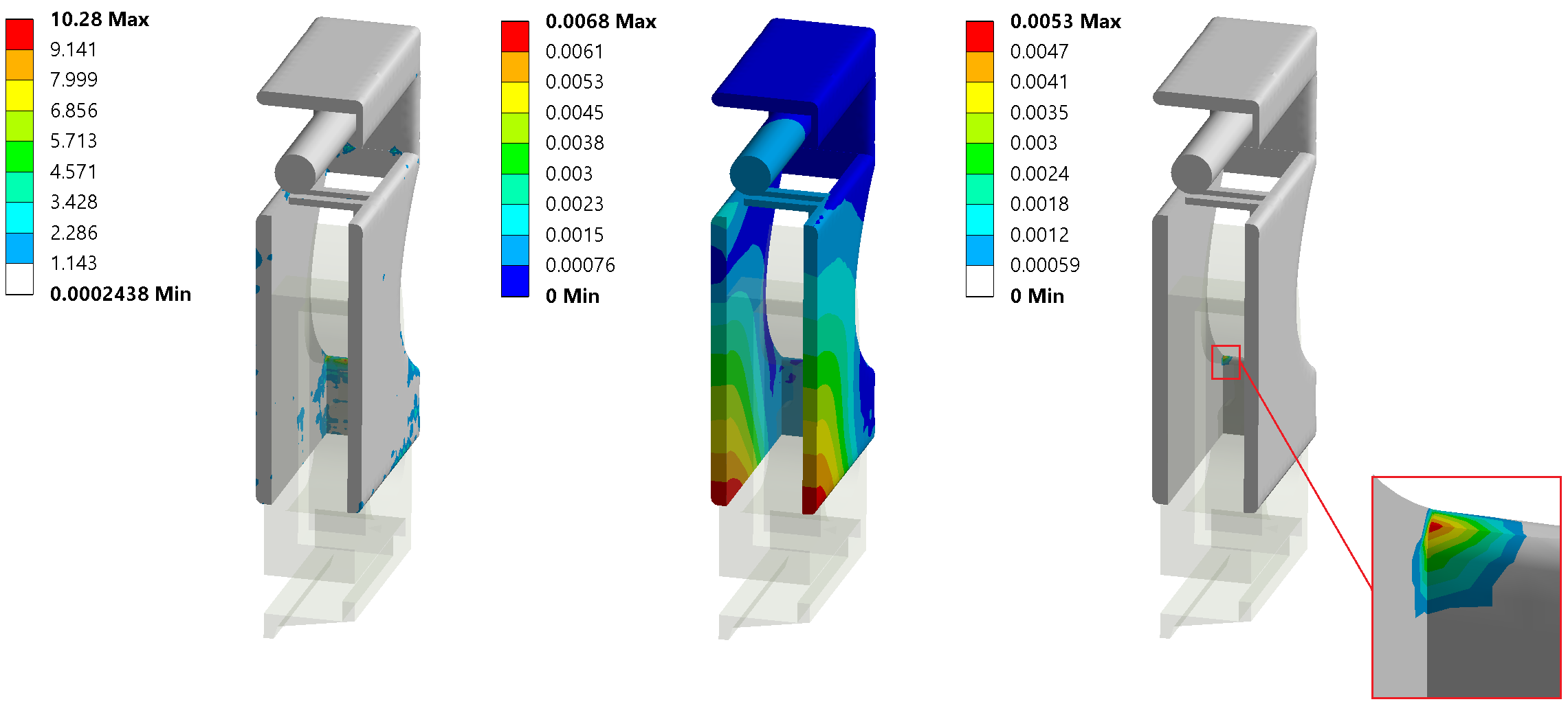
In the same manner, results on the upper component can be seen in Figure 6. Equivalent stress distribution is shown in Figure 6a, total deformation distribution in Figure 6b and plastic strain distribution with a detail showing maximal plastic strain location in Figure 6c.
It can be seen that maximal stress, maximal deformation and maximal plastic strain all appeared on the lower component of the buckle assembly. Maximal stress on the lower component appeared at the location of highest geometrical discontinuities, namely on the thinnest part of the component. However, the obtained stress value still does not exceed tensile yield strength of the considered material (44 MPa). This means that no yielding should occur. Maximal plastic strain on the lower component is 12%, which is significantly above the plastic strain limit of the considered material at room temperature (0.35%).
Conclusion
A semi-implicit analysis of a polymer bicycle helmet buckle was conducted in order to predict the behaviour of the buckle during snapping. Deformation of the buckle, plastic strain and stress concentration locations were determined. It was shown that the highest stress is still below the yield strength of the considered material, but the highest plastic strain is significantly above the plastic strain limit of the material used in the calculation. It can be concluded that for that reason, the lower part of the buckle has high plastic deformation. Also, after interlocking with the upper part, it does not come to an appropriate position. In order for the buckle to function properly, its design should be modified in a way that would reduce the plastic strain of the lower part of the buckle.
References
[1] Ansys 2020R1 Help Documentation, 2020.