ABSTRACT
Inductive coupling based wireless power transfer is a popular short-range power delivery mechanism for wide range of electric gadgets. The advances of this technology make it very desirable to the electric vehicle charging applications in both stationary and dynamic charging scenarios. In this work, the performance of a two-coil wireless power transfer system is analysed. To describe the wireless power charger system, a simulation model is developed that combined an electrical circuit with a nonlinear finite element model. We introduce a simulation method for wireless power transfer system design with ANSYS software suite.
Introduction
In the last few years, the industry has shown an increasing interest in the possibility to charge electric equipment wirelessly. Application that have accelerated the development of wireless power transfer (WPT) are medical implants, mobile devices such as laptops and cell phones and electric vehicles.
Wireless charging station at parking lots could ensure that your electric vehicle is charging or electric trucks in a warehouse can operate continuously if the floor is equipped with wireless charging tracks. However, simultaneously high efficiency and high-power transfer in WPT systems have proven difficult to achieve over moderate air gap between the transmitter and receiver coil.
The short-distance wireless energy transfer is either based on capacitive or inductive coupling. However capacitive coupling energy transfer is limited by low power transfer. Inductive coupling uses the magnetic field which can stored larger energy than electric field. A method of improving the performance of coupling for larger distance is to utilize resonant circuits for transmitter and receiver side of WPT system (Reuben, Leo & Charles 1988) (Rikard 2015).
2. In the following, we briefly describe the frequency and time domain analysis of wireless power transfer system included a large-gap transformer as finite element model. Figure 1. shows the main parts of the large-gap transformer.

The halved geometry of the wireless power transfer structure.
Frequency domain analysis of the wireless power transfer system
The study of the wireless power transfer system is split up in two main parts, the determination of resonance frequency of the two (transmitter and receiver) resonating circuits and the entire charger system time domain analysis.
In this study the transmitter coil can be configured with series capacitor, and the receiver part uses parallel resonance (Mehdi & Maysam 2012). The frequency domain analysis of circuit model is realized in ANSYS Simplorer system simulator, where AC resistance, self- and mutual inductance can be determined by finite element method (Kuczmann & Iványi 2008) using ANSYS Maxwell.
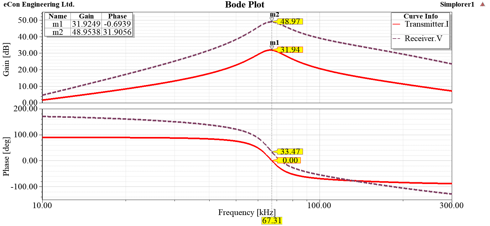
The results of the analysis can be seen in Figure 2. The current will be maximum at resonance in series resonance circuit (Mehdi & Maysam 2012), therefore the resonance frequency is 67.31kHz as you can see in Figure 2. In the parallel resonance receiver side, the voltage should be maximum. The phase shift is due to inductive coupling.
Time domain analysis of the charging system
With the knowledge of the resonance frequency, the entire charging system can be analysed. The resonance frequency is required to

Results of frequency domain analysis via ANSYS Maxwell and Simplorer cosimulation.

Vehicle charging system with wireless power transfer.
control the inverter. The entire charging system included the WPT system can be seen in Figure 3.
The entire system consists of a three-phase power supply, a three-phase diode rectifier, a single-phase full bridge inverter, the wireless power transfer system with the finite element model of large-gap transformer and the battery with two-phase rectifier.
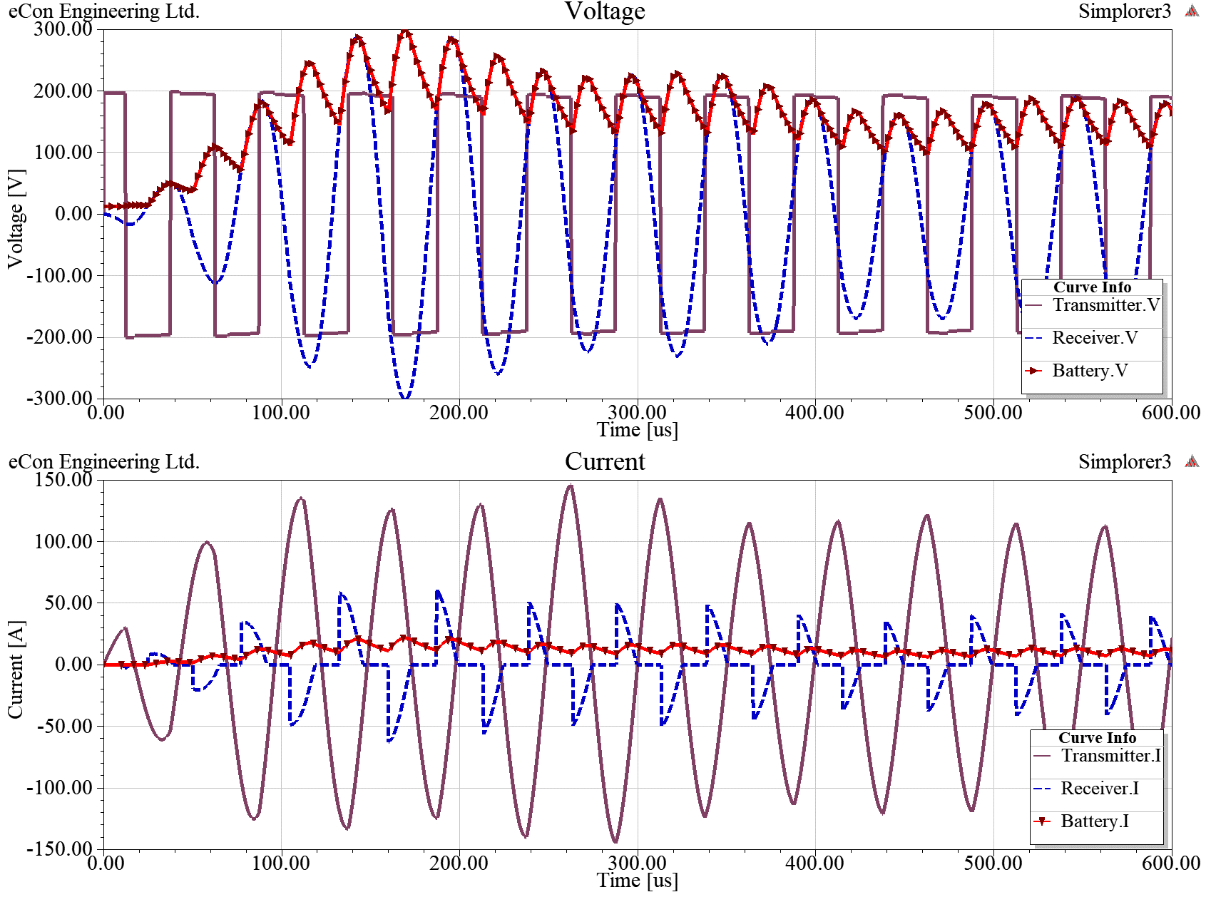
The excitation of the WPT system is a pulse width modulated signal as you can see in Figure 4. The frequency of this signal is the resonance frequency. Figure 4. also shows the voltage and current waveforms of receiver coil and battery.
Conclusions
This study has introduced a method of simulating inductive coupling based wireless charging system in ANSYS software suite for electric and hybrid vehicles. The simulation results show that the designed
 Results of time domain analysis via ANSYS Maxwell and Simplorer cosimulation.
WPT system is work properly in the wireless charger.
Our future plan is to take into account the stress and thermal effect of the coils and the effect of high frequency far field.
References
Kuczmann, M. & Iványi, A., 2008, The Finite Element Method in Magnetics, Akadémiai Kiadó, Budapest.
Mehdi, K. & Maysam, G, 2012, ‘The Circuit Theory Behind Coupled-Mode Magnetic Resonance-Based Wireless Power Transmission’, IEEE Transactions on Circuit and Systems – I: Regular Paper 59(9), pp. 2065-2074.
Reuben, L., Leo, W. & Charles, E.C., 1988, Electronic Transformers and Circuits, 3rd Ed., Wiley-Interscience, New York.
Rikard, V., 2015, ‘Wireless Energy Transfer by Resonant Inductive Coupling’, Master thesis, Dept. of Signals and Systems, Chalmers University of Technology.
by Dr. Dániel Marcsa


